BURCHDA E-Bike display manual - KD926
KD926 is currently used in BURCHDA HC26 and BURCHDA RX80 dual-motor electric bicycles.
Please note:
This manual is for reference only. Due to the continuous upgrading of ebikes, the content may be outdated. Please refer to the manual provided with the ebike for details.
Since the factory settings of ebikes can meet most usage scenarios, ordinary users generally do not need to read this more complicated manual.
Product Name and Model
Intelligent LCD display for E-bike; model:KD926
Specifications
●36V/48V Power Supply
●Rated working current:25mA
●The maximum working current:30mA
●Off leakage current:<1uA
●Supply the working current of the controller:50mA
●Operating temperature:-20~60℃
●Storage temperature:-30~70℃
Appearance

Function Summary
KD926 can provide a lot of functions to fit your needs. The indicating contents are as
follows:
●Battery capacity indicator
●Motor power indicator
●PAS level adjustment and indicator
●Speed indicator (incl. real speed, Max. speed and Avg. speed)
●Distance(Trip and ODO)
●6km/h push assistance
●Trip time
●Backlight
●Error code
●USB connection
●Various Parameters Settings (e.g., wheel size, speed-limited, battery capacity
setting, assistance level parameter setting, power-on password settings, controller current limiting settings etc.)
●Default parameter recovery function
Functional area

Definition of Button
The KD926 display matches the K5 button. K5 has 5 buttons: including on/off, i key,
plus key, headlight key, minus key/boost key; in the subsequent description, the on/off key
uses the word "ON/OFF" replace; the i button is replaced with the word "i"; the plus button
is replaced with the word "UP"; the minus/boost button is replaced with the word "DOWN".
General Operation
◆Power on/off
After long pressing the "ON/OFF" button for 2 seconds, the display starts to work and
provides working power to the controller. In the power-on state, press and hold the
"ON/OFF" button for 2 seconds to turn off the power of the e-bike. In the shutdown state, the display no longer uses battery power, and the leakage current of the meter is less than 1uA.
■When parking the E-bike for more than 5 minutes, the E-bike system switches off automatically
◆Display Interface
After the display is turned on, the display shows real-time speed (km/h) and Trip(km)
by default. Short press the "i" button to display information on TRIP (km), ODO (km), TIME (min), MAX speed (km/h), average speed AVG (km/h), Switch between cycles.

◆6km/h Push-assistance
power-assisted driving state. The e-bike travels at a constant speed of 6km/h. At the same time, the screen displays "
 ". Release the "DOWN" button and the e-bike will
immediately stop power output and return to the state before boosting. Execution is only enabled in PAS level 0.

■The power-assisted push function can only be used when the user is pushing the e-bike please do not use it while riding.
◆Turn on/off backlight
controller to turn on the headlights. When the external light is insufficient or
driving at night, the LCD backlight can be turned on. Click the "Headlight"
button again to turn off the LCD backlight and notify the controller to turn off the headlights.

◆PAS level
the motor output power. The default range of the display is PAS level 0-5, PAS level 0 is
unassisted, PAS level 1 is the lowest power, and PAS level 5 is the highest power. When
reaching level 5, short press the "UP" button again, and the interface still displays 5. After the power-assisted downshift reaches 0, short press the "DOWN" button again, and the interface still displays 0.

◆Motor selection
Long press the "i" button, switch the front and rear motors, change the motor output
mode, the instrument is divided into front drive, rear drive, dual drive, no drive, the
default range is rear drive.

◆Battery capacity
flashes), 10%, 20%, 30%, 40%, 50%, 60%, 70%, 80%, 90%, and 100% power. state.

Battery capacity interface
◆USB Connection
When the display is plugged into a USB external device, the display will show the
interface in the figure below.

◆Brake display
When the e-bike brakes, the display show mode is as shown in the following figure.

◆Cruise control display
Press and hold the minus key in non PAS level 0, and when the display enters cruise control, the display show is as shown in the figure below.

◆Error code
When the electronic control system fails, it will automatically display the error code.
Here is the detailed message of the error code in Attached list 1.

■When an error code is displayed, please remove the fault in time, the e-bike will not
be able to run normally after a fault occurs
General setting
Long press the "ON/OFF" button to turn it on. In the power-on state, when the e-bike
is stationary, press and hold the UP" and "DOWN" buttons for more than 2 seconds to
enter the normal setting state.
◆Trip reset
"DOWN" button. Y means reset the trip. N means not reset the trip; short press the "i"
button.

◆ODO reset
OC stands for ODO reset, the customer can be selected through the "UP" or "DOWN"
button choose Y/N. Y means reset ODO. N means not reset ODO; short press the "i"
button.

◆Light sensitivity
sensitivity can be switched between 0FF and 1-5 levels, with the default level 3; 0FF
represents: turning off the light sensor function. The default is OFF, short press the "i" key to confirm and enter the next setting interface.

◆Backlight brightness
bL represents backlight brightness. Parameters 1, 2, and 3 can be set to indicate the
backlight brightness. 1 is the darkest, 2 is the standard brightness, and 3 is the brightest.
The default brightness of the display is 3. The backlight brightness parameters can be
changed through the "UP" or "DOWN" button, short press the "i" button to confirm, long press the "i" button to confirm and exit the regular setting state.

◆Toggle Unit
U represents the unit, 1 represents the imperial system, and 2 represents the metric
system. The speed and mileage units can be converted through the "UP" or "DOWN"
button, short press the "i" button to confirm, long press the "i" button to confirm and exit the general setting state. The default unit of the meter is 2 metric

◆Automatic shutdown time Settings
ATF indicates the automatic shutdown time. You can set the automatic shutdown time
of the display. 1 indicates 1min, 5min is the default shutdown time, and 10min is the
longest shutdown time. Press the UP or DOWN button to change the automatic shutdown time parameters. Press and hold down the i button to confirm and exit the general setting.

◆Restore default settings
dEF stands for restoring default parameters. There are two ways to restore factory
Settings:
1. Press UP or DOWN to switch Y/N. Y indicates that default parameters need to be
restored, N indicates that default parameters do not need to be restored. If Y is selected, hold down i for more than 2 seconds to confirm.
2. On the startup password screen, hold down the i key for at least two seconds.
The instrument will automatically start to restore the default Settings and display dEF-00, and automatically exit and return to the normal display interface after the default is
restored.

Wheel diameter speed limited parameter setting
Press and hold the "UP" and "DOWN" buttons for more than 2 seconds and lift them up to enter the regular setting state. Then press and hold the "i" and "DOWN" buttons at the same time for more than 2 seconds to enter the wheel diameter setting interface and speed limit setting interface.
◆Wheel diameter setting
LD indicates the wheel diameter setting. The wheel diameter setting range is 18inch
to 29 inch. The default wheel diameter is 28inch. Press i to save the settings and go to the next interface.

◆Speed limited setting
LS indicates the rate limit setting. The value range is 12-99 km /H. The default rate
limit is 45KM/H. Press i to save the settings and go to the next interface

Speed limited setting interface
Advanced parameter settings
them up to enter the general setting state. Then press and hold the "UP" and "DOWN"
buttons simultaneously for more than 2 seconds to enter the advanced setting interface.
◆Battery capacity setting
by one. Take the first power value as an example: "1" on the screen represents the first
voltage, and "40.0" is the first power value. Use "UP" or " DOWN" button to add/subtract to change the value, short press the "i" button to confirm and enter the next power setting interface; after the 10 power value settings are completed, long press the "i" button to confirm and return to the instrument setting item selection interface.

◆PAS level range setting
By setting the help ratio value, the speed of each gear can be adjusted to meet the needs of different riders. Take the first gear as an example, "50%" is the default value of the first gear, which is a configurable value. Press "UP" or "DOWN" to add/subtract Settings, press "i" to confirm and enter the next boost ratio setting, a maximum of 9 can be set. After the setting is complete, press and hold "i" to confirm and return to the screen for selecting instrument Settings.
Refer to Schedule 2 for details.

◆Current limiting setting
CUR indicates current limit, current range 6A-30A, default 25A. You can adjust current limit by pressing "UP" or "DOWN". After setting, press and hold "i" to confirm and return to the interface for selecting display Settings.

◆Speed magnet number setting
of magnetic steel of the measurement sensor is 1-15, the default is 1, the number of
magnetic steel of the measurement sensor can be adjusted by the "UP" or "DOWN"
button, after the setting is completed, long press the "i" button to confirm and return to the display setting item selection interface.

◆PAS sensor sensitivity setting
SCN represents the sensitivity of the boost sensor. The sensitivity range of the PAS sensor is 2-9, and the default is 2. The sensitivity of the PAS sensor can be adjusted through the "UP" or "DOWN" button. After the setting is completed, press and hold the "i" button to confirm and return to the display setting item selection interface.

◆PAS sensor magnet number setting
PAS indicates the number of magnets for the PAS sensor. The range of magnets for the
power sensor is 4-9/12/24/32. The default value is 12. You can press UP or DOWN to adjust the number of magnets for the power sensor.

◆Power-on password setting
displayed, indicating the startup password. Press the "i" button to shift, and press the "UP" or "DOWN" button to add or subtract the input value. After entering the 4-digit password, press the "i" button to confirm. If the password is correct, the screen for enabling or disabling the startup password is displayed. The default startup password is 1212. The password is disabled.

Press the UP or DOWN button to select Y, and P3 is displayed. Press the i button to
shift, and add or subtract a value by pressing the UP or DOWN button. Press and hold
down the i key to save the Settings and exit the setting screen. After restarting the display P1, 0000 will be displayed. Only after entering the correct password can let the display work normally.

Power-on password setting interface
Display information interface
Long press the "UP" and "DOWN" buttons for more than 2 seconds to lift, enter the
general setting state. Hold DOWN and hold DOWN the UP and Down buttons for more
than 2 seconds to enter the advanced Settings screen. Hold down and hold down the UP and Down buttons for more than 2 seconds to view the display software information.
Press and hold DOWN the "UP" and "Down" buttons at the same time for more than 2
seconds to view the hardware information of the display.

Exit setup
save the current setting; Hold down the i button (more than 2 seconds) to save the current setting and exit the current setting state. Hold DOWN the Down button for more than 2 seconds to cancel the current operation and exit the setting. The current setting data is not saved.
■If no operation is performed within one minute, the instrument automatically exits the
setting state.
Connection Layout

Attached list 1:Error code definition
| Error code | Definition |
| 21 | Current Abnormality |
| 22 | Throttle Abnormality |
| 23 | Motor phase |
| 24 | Motor Hall signal abnormality |
| 25 | Abnorma l braking |
| 30 | Communication abnormality |
-
48V31.5Ah Original Battery for Burchda U8
Regular price €549,00 EURRegular priceUnit price per€589,00 EURSale price €549,00 EURSafe & Secure Payments


 Sale
Sale -
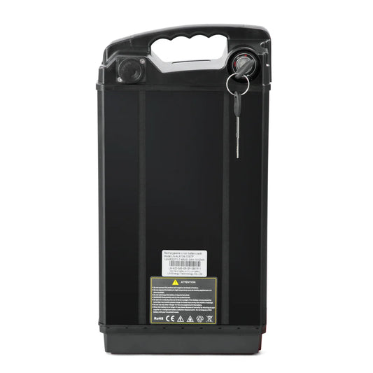
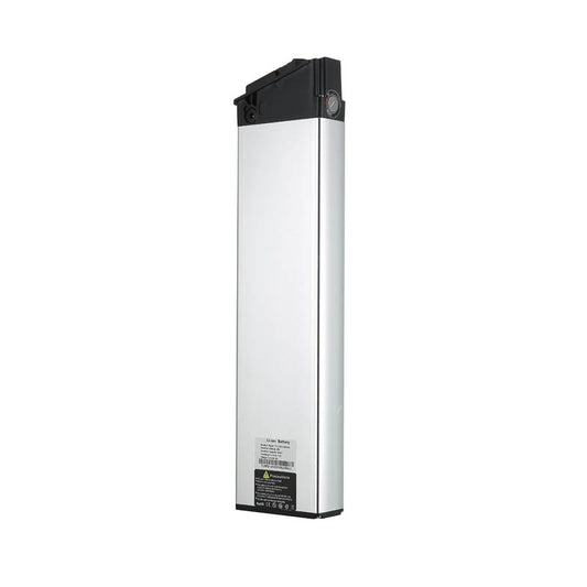
48V30Ah Original Battery for Burchda HC26
Regular price €499,00 EURRegular priceUnit price per€559,00 EURSale price €499,00 EURSafe & Secure Payments
Sale -
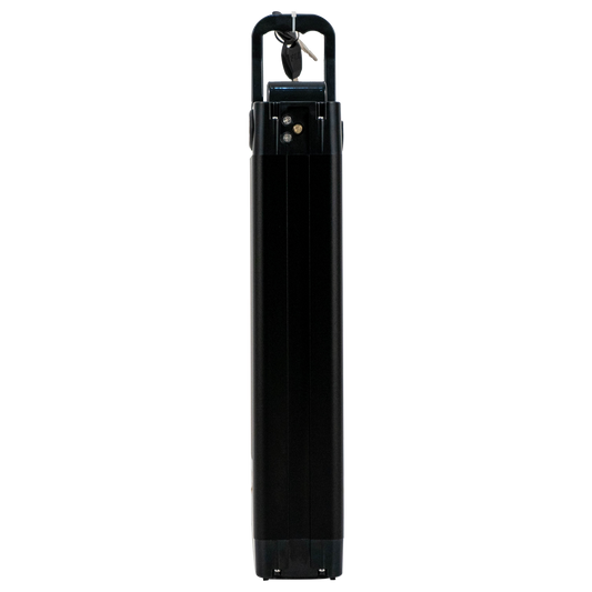
48V 17.5Ah Original Battery for Burchda RX90
Regular price €429,00 EURRegular priceUnit price per€499,00 EURSale price €429,00 EURSafe & Secure Payments
Sale -
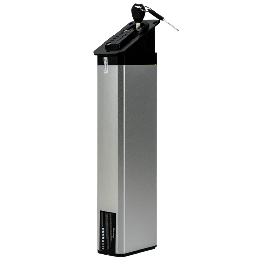
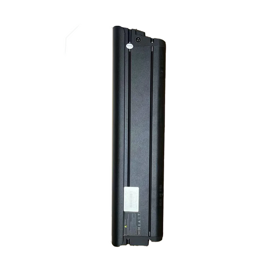
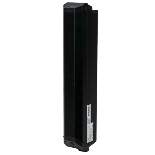
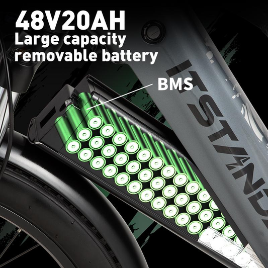
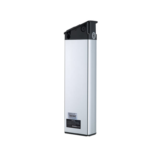
Original Battery for Burchda RX80/RX50/AZ20
Regular price €419,00 EURRegular priceUnit price per€459,00 EURSale price €419,00 EURSafe & Secure Payments
Sale -
48V20Ah Original Battery for Burchda R5Pro
Regular price €409,00 EURRegular priceUnit price per€449,00 EURSale price €409,00 EURSafe & Secure Payments
Sale -
48V 20Ah Battery for Burchda AZ26
Regular price €399,00 EURRegular priceUnit price per€449,00 EURSale price €399,00 EURSafe & Secure Payments
Sale -
48V20Ah Original Battery for Burchda RX70/RX20
Regular price €399,00 EURRegular priceUnit price per€459,00 EURSale price €399,00 EURSafe & Secure Payments
Sale -
48V20Ah Original Battery for Burchda Itsands RX26
Regular price €389,00 EURRegular priceUnit price per -
48V17.5Ah/48V20Ah Battery For Burchda /Jinghma R7 Pro
Regular price From €389,00 EURRegular priceUnit price per -
Original Battery For Burchda R8/R8S/R8SPro/R8Pro
Regular price From €359,00 EURRegular priceUnit price per€379,00 EURSale price From €359,00 EURSafe & Secure Payments
Sale -
48V15Ah Original Battery for Burchda RX02/H1
Regular price €339,00 EURRegular priceUnit price per -
Original Battery for Burchda R3 PRO/R3
Regular price From €339,00 EURRegular priceUnit price per€329,00 EURSale price From €339,00 EURSafe & Secure Payments
-
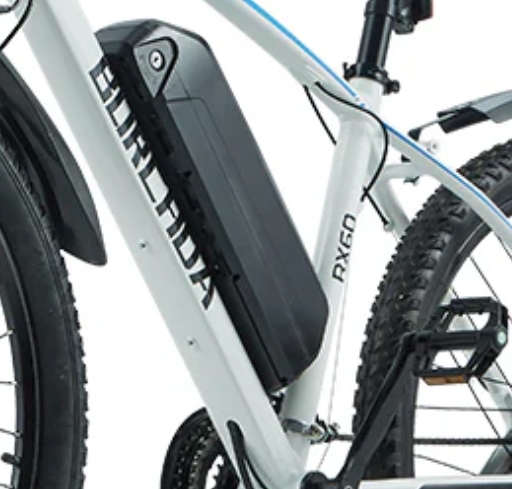
48V15Ah Original Battery for Burchda RX60
Regular price €299,00 EURRegular priceUnit price per€329,00 EURSale price €299,00 EURSafe & Secure Payments
Sale -
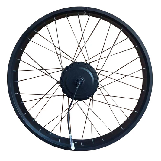
Original Rear Wheel Set (With Motor) For Burchda E-bike
Regular price From €249,00 EURRegular priceUnit price per -
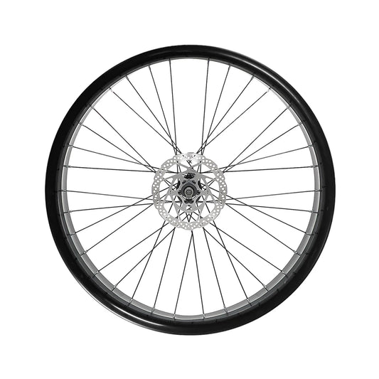
Original Front Wheel Set For Burchda E-bike
Regular price From €239,00 EURRegular priceUnit price per€229,00 EURSale price From €239,00 EURSafe & Secure Payments
-
Original Rear Wheel Set For Burchda E-bike
Regular price €229,00 EURRegular priceUnit price per -
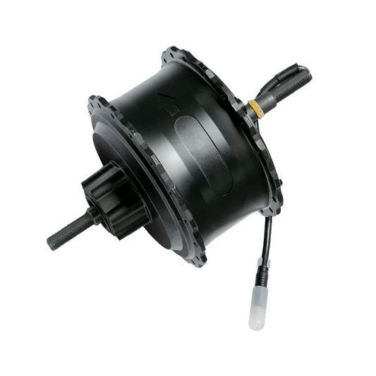
Original Motor Core for Burchda E-bikes
Regular price From €199,00 EURRegular priceUnit price per€299,00 EURSale price From €199,00 EURSafe & Secure Payments
Sale -
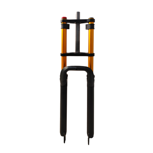
Front Fork Shock Absorber For Burchda E-bikes
Regular price From €159,00 EURRegular priceUnit price per€169,00 EURSale price From €159,00 EURSafe & Secure Payments
Sale -
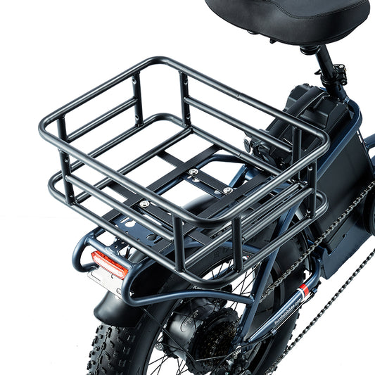
Rear Storage Basket for BURCHDA E-bikes
Regular price €129,00 EURRegular priceUnit price per€119,00 EURSale price €129,00 EURSafe & Secure Payments
-
Original Lower Fork for Burchda E-bikes
Regular price €119,00 EURRegular priceUnit price per€129,00 EURSale price €119,00 EURSafe & Secure Payments
Sale -
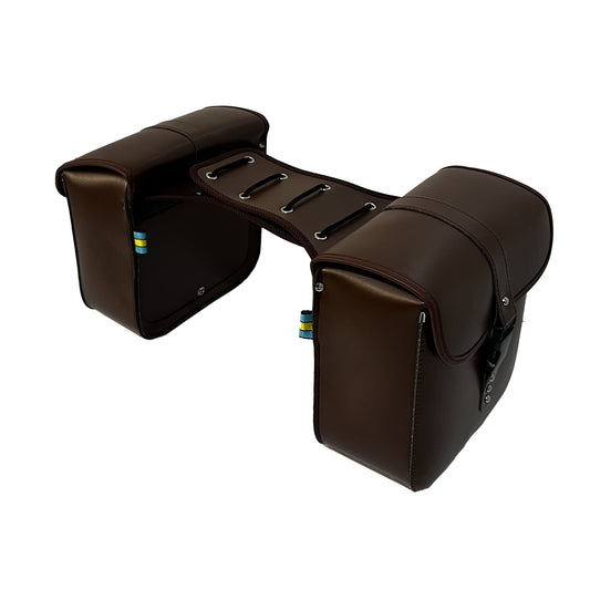
Burchda E-Bike Brown Leather Bag Durable Travel Bike Bag Mountain Bike Bag Luggage Bag
Regular price €119,00 EURRegular priceUnit price per€109,00 EURSale price €119,00 EURSafe & Secure Payments
Sold out -
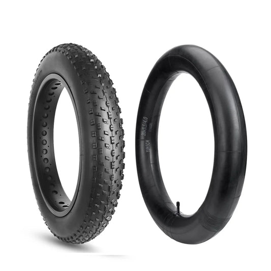
Burchda electric bike original inner and outer tires
Regular price €109,00 EURRegular priceUnit price per -
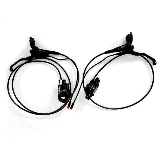
Original Hydraulic Brake / Mechanical Brake System For Burchda E-bikes
Regular price €109,00 EURRegular priceUnit price per -
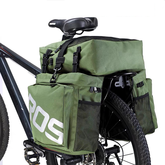
3 In 1 Trunk Bags Double Side for BURCHDA E-bike
Regular price €109,00 EURRegular priceUnit price per€119,00 EURSale price €109,00 EURSafe & Secure Payments
Sale -
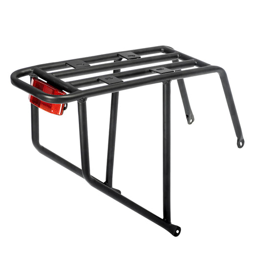
Original rear rack for Burchda E-bikes
Regular price €99,00 EURRegular priceUnit price per


-
 €200OFF
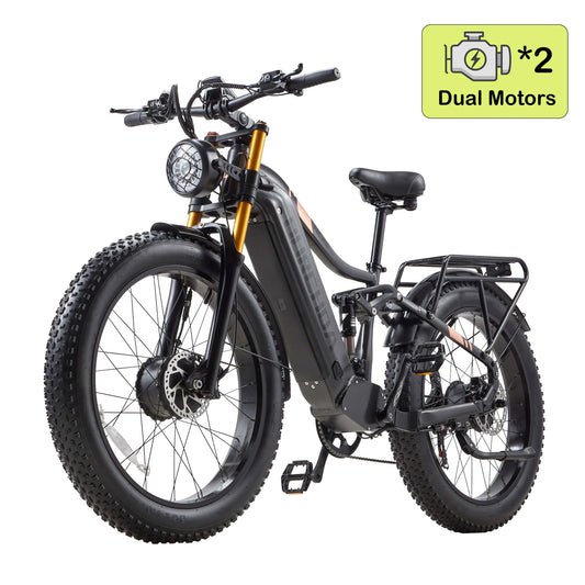
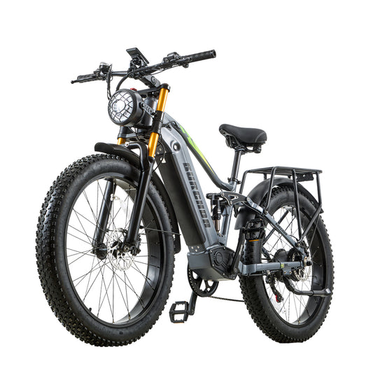
Burchda HC26 AWD
 2500W Brush-Less Motor
 48V30Ah UL certification
 100km Max Electric Range
 50km/h Max SpeedRegular price From €1.599,00 EURRegular priceUnit price per
€1.799,00 EURSale price From €1.599,00 EURSafe & Secure Payments
Sale -
 €370OFF
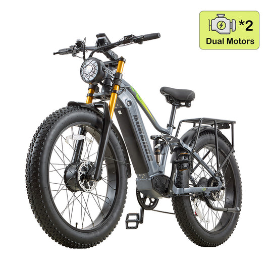
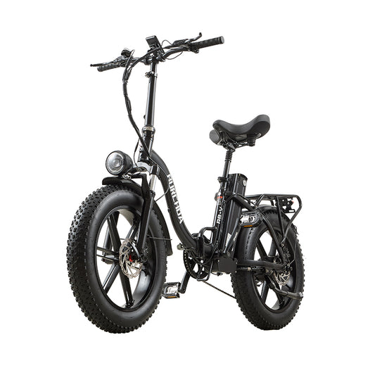
Burchda RX80 Dual Motor(Upgraded)
2000W Brush-Less Motor
48V 20Ah UL certification
65KM Max Electric Range
50KM/h Max SpeedRegular price From €1.329,00 EURRegular priceUnit price per€1.699,00 EURSale price From €1.329,00 EURSafe & Secure Payments
Sale -
 €400OFF
Burchda B27(2026 New Arrival)
1000W Brush-Less Motor
48V20Ah UL certification
80KM Max Electric Range
45KM/h Max SpeedRegular price From €1.499,00 EURRegular priceUnit price per€1.899,00 EURSale price From €1.499,00 EURSafe & Secure Payments
Sale -
 €200OFF
Burchda AZ26(2026 Upgraded)
1000W Brush-Less Motor
48V20Ah UL certification
65KM Max Electric Range
45KM/h Max SpeedRegular price From €1.099,00 EURRegular priceUnit price per€1.299,00 EURSale price From €1.099,00 EURSafe & Secure Payments
Sale -
 €250OFF
Burchda AZ20
1000W Brush-Less Motor
48V20Ah UL certification
65KM Max Electric Range
45KM/h Max SpeedRegular price From €1.199,00 EURRegular priceUnit price per€1.449,00 EURSale price From €1.199,00 EURSafe & Secure Payments
Sale -
 €350OFF
Burchda U8(2026 Upgraded)
1000W Brush-Less Motor
48V31.5Ah UL certification
100KM Max Electric Range
45KM/h Max SpeedRegular price From €1.299,00 EURRegular priceUnit price per€1.649,00 EURSale price From €1.299,00 EURSafe & Secure Payments
Sale -
 €400OFF
Burchda RX26(2026 New Arrival)
1000W Brush-Less Motor
48V20Ah UL certification
65KM Max Electric Range
45KM/h Max SpeedRegular price From €1.149,00 EURRegular priceUnit price per€1.549,00 EURSale price From €1.149,00 EURSafe & Secure Payments
Sale -
 €570OFF
Burchda X27(2026 New Arrival)
750W Brush-Less Motor
48V 17.5Ah UL certification
60KM Max Electric Range
40KM/h Max SpeedRegular price €1.029,00 EURRegular priceUnit price per€1.599,00 EURSale price €1.029,00 EURSafe & Secure Payments
Sale -
 €300OFF
Burchda R7 Pro Dual Motor
2000W Brush-Less Motor
48V20Ah UL certification
65KM Max Electric Range
45KM/h Max SpeedRegular price From €1.099,00 EURRegular priceUnit price per€1.399,00 EURSale price From €1.099,00 EURSafe & Secure Payments
Sale -
 €240OFF
Burchda RX02
1000W Brush-Less Motor
48V15Ah UL certification
60KM Max Electric Range
45KM/h Max SpeedRegular price From €849,00 EURRegular priceUnit price per€1.089,00 EURSale price From €849,00 EURSafe & Secure Payments
Sale -
 €250OFF
Burchda RX20(2026 Upgraded)
1000W Brush-Less Motor
48V20Ah UL certification
65KM Max Electric Range
45KM/h Max SpeedRegular price €1.039,00 EURRegular priceUnit price per€1.289,00 EURSale price €1.039,00 EURSafe & Secure Payments
Sale -
 €370OFF
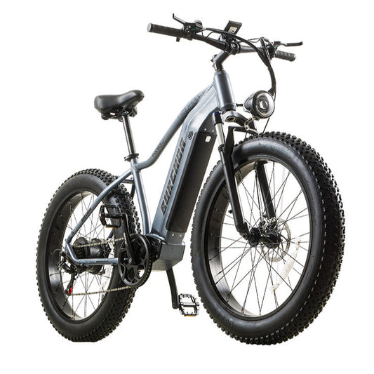
Burchda RX80(Upgraded)
1500W Brush-Less Motor
48V20Ah UL certification
65KM Max Electric Range
45KM/h Max SpeedRegular price From €1.329,00 EURRegular priceUnit price per€1.699,00 EURSale price From €1.329,00 EURSafe & Secure Payments
Sale -
 €250OFF
Burchda R7 Pro (2026 Upgraded)
1000W Brush-Less Motor
48V120Ah UL certification
55KM Max Electric Range
45KM/h Max SpeedRegular price From €1.099,00 EURRegular priceUnit price per€1.349,00 EURSale price From €1.099,00 EURSafe & Secure Payments
Sale -
 €190OFF
Burchda R8S Pro / R8V
1000W Brush-Less Motor
48V20Ah UL certification
65KM Max Electric Range
40KM/h Max SpeedRegular price From €1.099,00 EURRegular priceUnit price per€1.289,00 EURSale price From €1.099,00 EURSafe & Secure Payments
Sale -
 Sold out
Burchda R3 (2026 Upgraded)
800W Brush-Less Motor
12.8Ah UL certification
45KM Max Electric Range
40KM/h Max SpeedRegular price From €849,00 EURRegular priceUnit price per€999,00 EURSale price From €849,00 EURSafe & Secure Payments
Sold out -
 Sold out
Burchda RX50
1000W Brush-Less Motor
48V17.5Ah UL certification
60KM Max Electric Range
45km/h Max SpeedRegular price From €1.099,00 EURRegular priceUnit price per


